WEEK
ELEVEN
INPUT DEVICES
Task for this week
Group Assignment
Probe an input device's analog levels and digital signals.Individual Assignment
Measure something: add a sensor to a microcontroller board that you have designed and read it.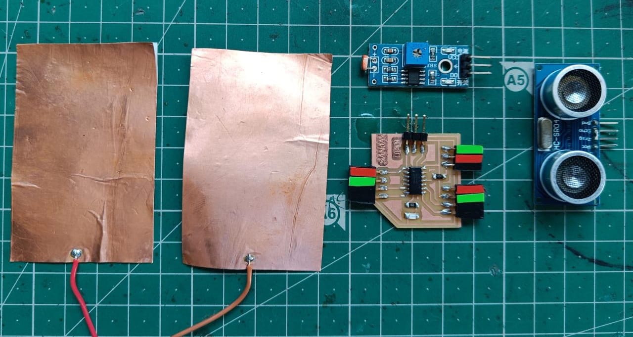
This week is for the input devices. For input devices we uses various type of sensor which read the atmospheric condition and give
the signal to the microcontroller. This signal is in the form of of analog signal or digital. Microcontroller read both the signal.
So for this week we have to designed a new board which is used for reading the data or signal from input devices.
What is of sensors ?
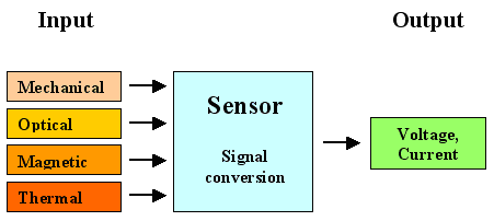
Sensors are the device which sense the respective quantity (for eample temperarture sensor measure the temperature) and convert this quantity into a electrical signal. This electrical signal may be in the form of digital or analog signal. This signal is read by microcontroller and then it give a value respective to that measure quantity.
How sensor works ?
Every sensor have three parts in it-1. Sensing section- This is the section where the sensor is there. This sensor are chosed to sense the magnitude of respective things which we want to measure.
2. Electronic circuit - Its second section are convert this measured values into electrical form. Means it convert the respective data into mV.
3.Output to microcontroller- The last part is transmite this measured data to the microcontroller in the form of digital or analog signal.
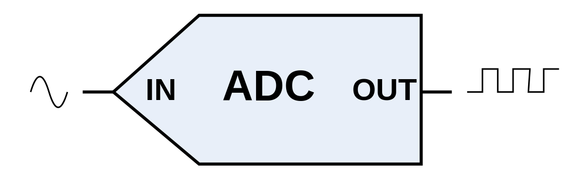
Analog to Digital Conversion
Mostly microcontroller support only digital signal. But our sensor output are in analog signal. So we have to convert this analog signal into digital signal.We used a Analog to digital convertor in microcontroller board by which microcontroller read the digital signal. At present most of the sensor have this convertor
on their output signal board by which we obtained both type of Analog and Digital signal.
Type of Sensors
Sensors are define in variou types according to their performance. Some of types are given below-1.Active and passive sensors
Active sensor
Active sensor are does not required any power or signal to operate. They also called generators. For example if we talk about thermocouple, it have only two wires does not have a power supply wire or connection. When the temperature become high or low, the voltage across these two wire changes. the voltage in the form of mV and it transmiited in the form of anolog signal to microcontroller.
Passive sensor
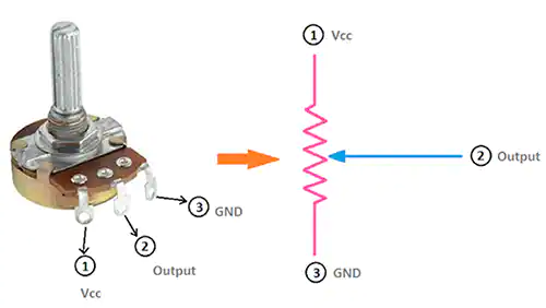
Passive sensor are required external power supply or extrenal signal to perform the operation. For example if we talk about the Potentiometerand load cell, they both come in category of passive device. They produced voltage and we read this voltage by microcontroller
2.Analog and Digital sensors
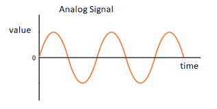
Analog sensor
The sensor which give output in the form of analog (which varries) are called analog sensor. The value of this analog sensor continouslychanges with respect to measuring quantity like temoerature , humidity etc.
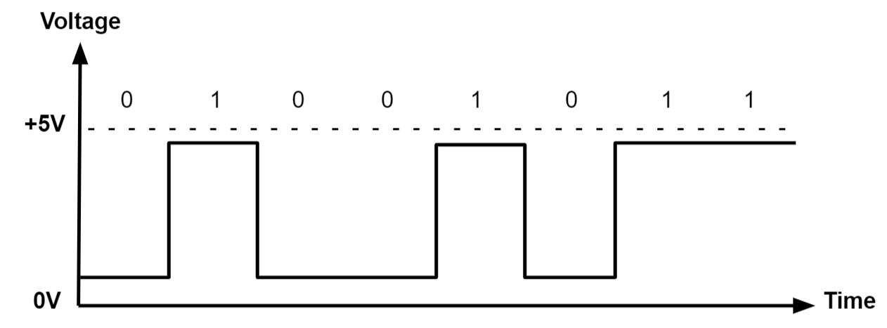
Digital sensor
The sensor which give the output in the form zero or one are called digital sensor.The value of this sensors are fixed ther give output of
either one or zero. example digital temperarure sensor.
3.Scaler and Vector sensor
Scaler sensor
The sensor which sense the quantity not direction are called scaler sensor. For example Temperature and gases measurement. We dont need any directionfor measure this.
Vector Sensor
The sensor which magnitude depends on the direction called Vector sensor. For Example Triple axis accelerometer which measure the magnitudeof the direction.
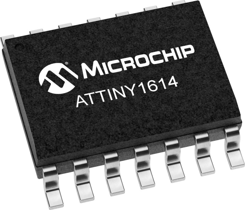
Attiny 1614
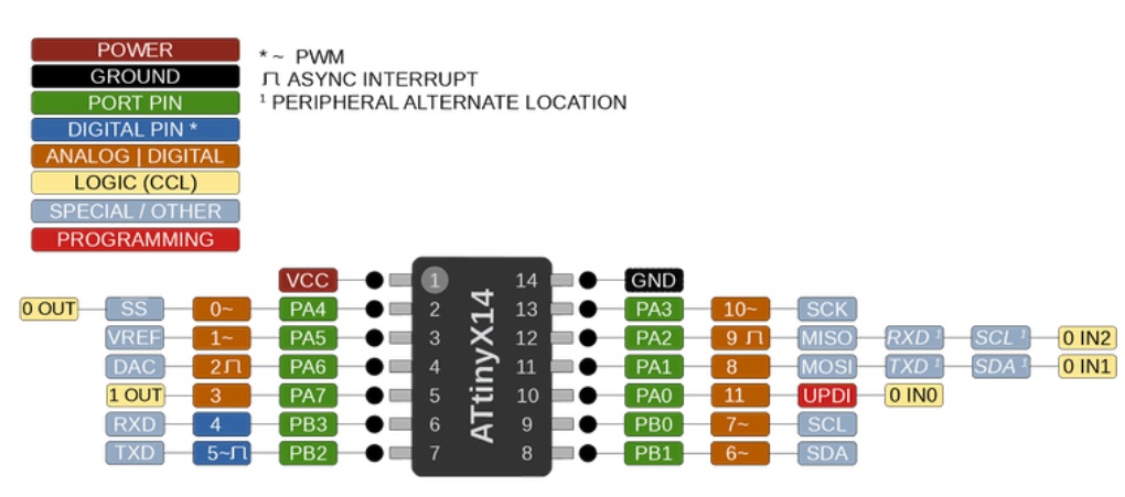
This time I selected Attiny 1614 for PCB Board. This is the 14 pin ic which is new series of Attiny Family. This IC is come with 8 bit AVR processor. This processor running at 20MHz. It have 16KB of flash memory, 2KB of SRAM memory and 128B EEPROM. It require Minimum voltage of 1.4 V and maximum voltage of 5.5V for the operations. It work in the temperature range between -40 C to 105 C.This Microcontroller have 14 Pins-
Board Design
For this week we have to design a new board for the input devices. Firstly I make the planing for which sensor I have to test with my microcontroller. According to it I designe my PCB. So I designed the PCB according to the sensor pins. I decided to test ultrasonic sensor, LDR sensor, PIR motion detector and Step response sensor Now according to My sensor pin requirements I select the pin header.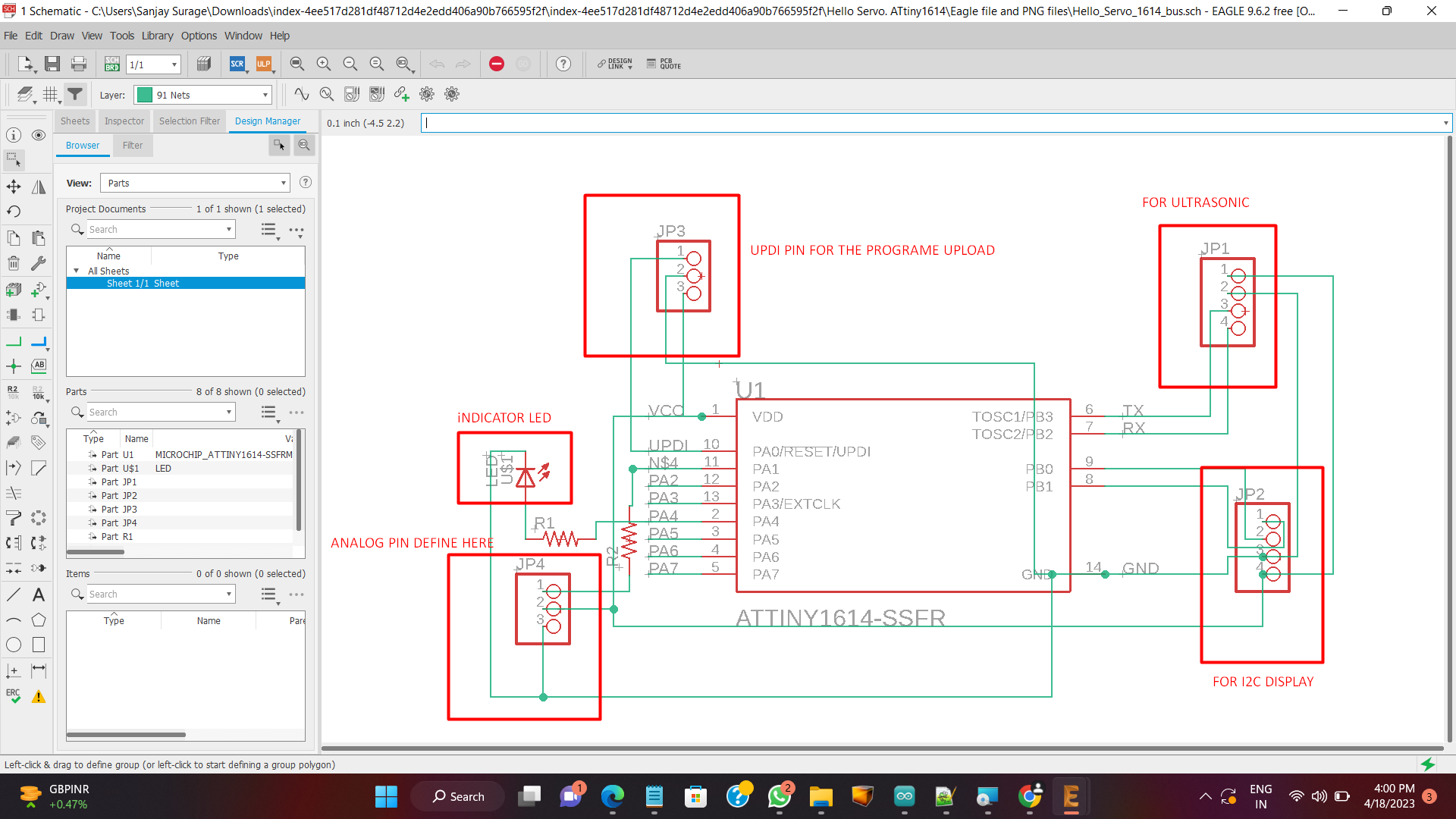
I select Three Pin header for the UPDI,VCC and GND and connect the UPDI pin to IC's Updi. Then I select 2 pin header of 4 pins. The one is used for the led display and another is used for the ultrasonic sensor. So I used SDA, SCL and Rx and Tx pin and then provide supply of GND and VCC to the both pin header. I also chosed another 3 pin header and connect its one pin to the 8 no. analog pin of Ic and provided supply of VCC and GND. I also used a LED by which I can understand about my board working or not. After that I change the schematic into board and arrange all the component in the proper manner.
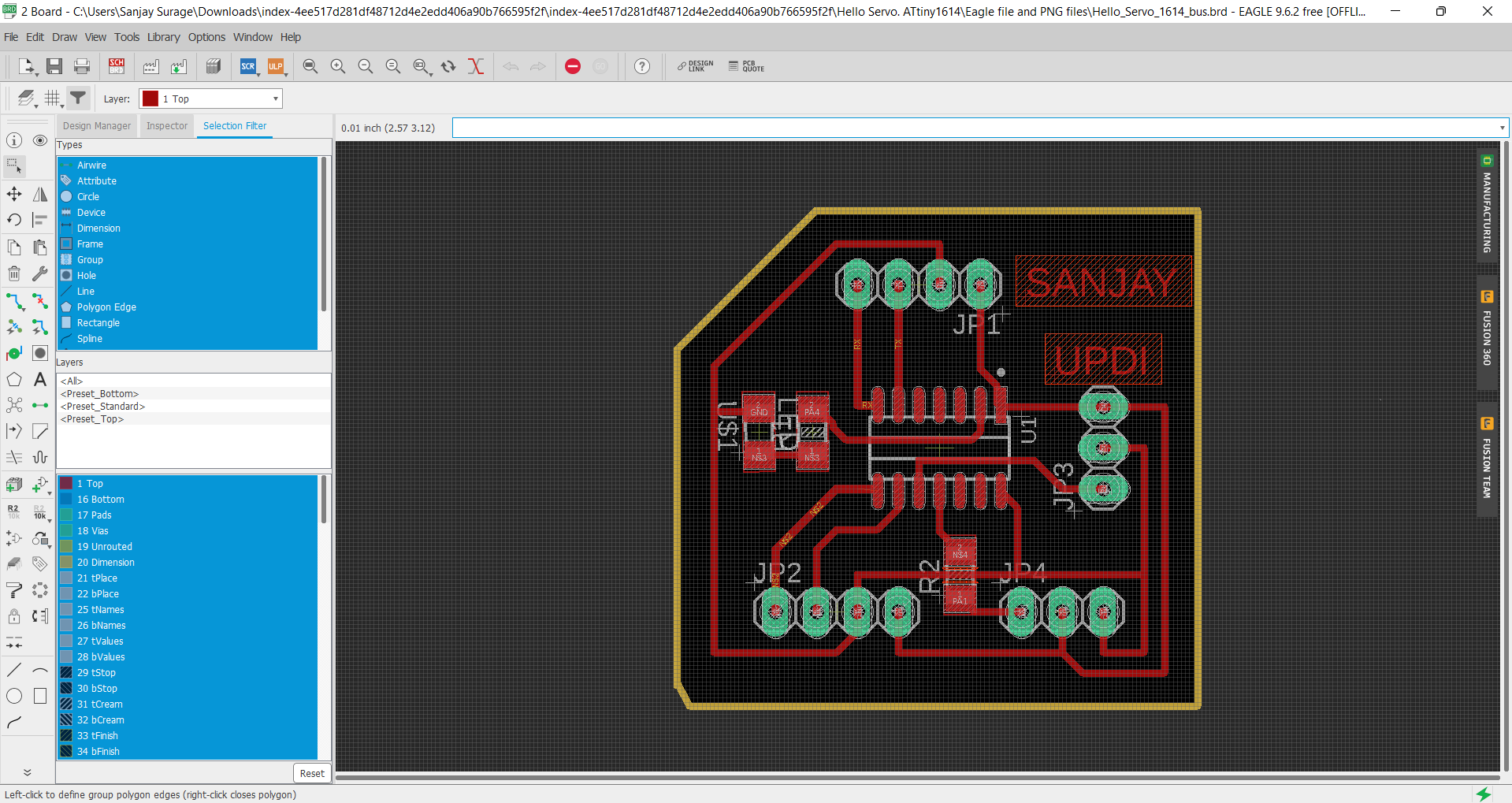
After arranging I Export the png files of that board.
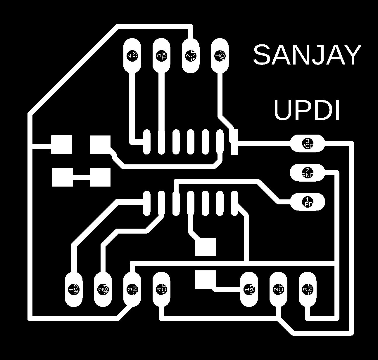

Then I generate the gcode for the my pcb board by usind MODs CE platform.
For the milling of traces-
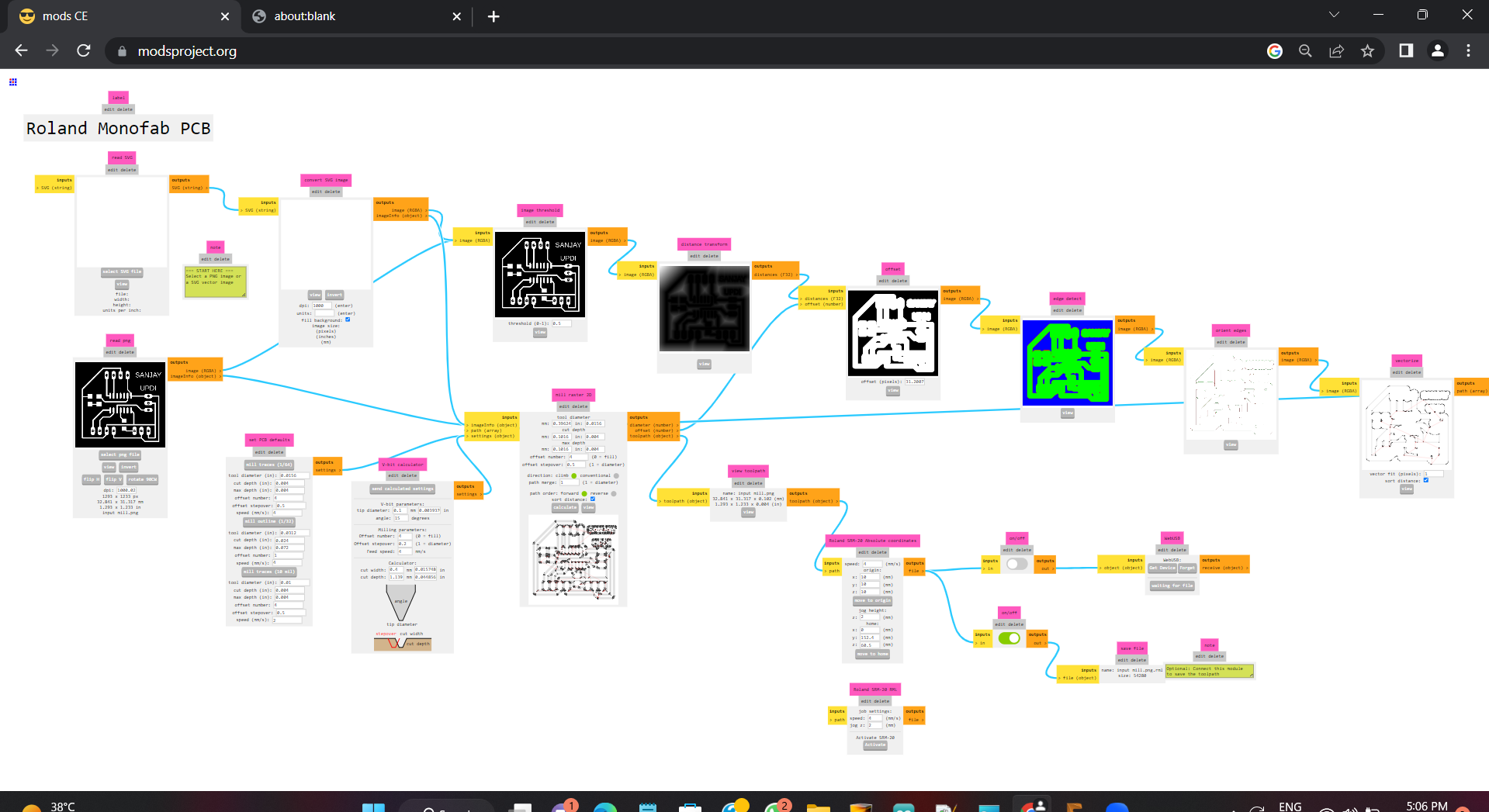
For the Border Cutting Process
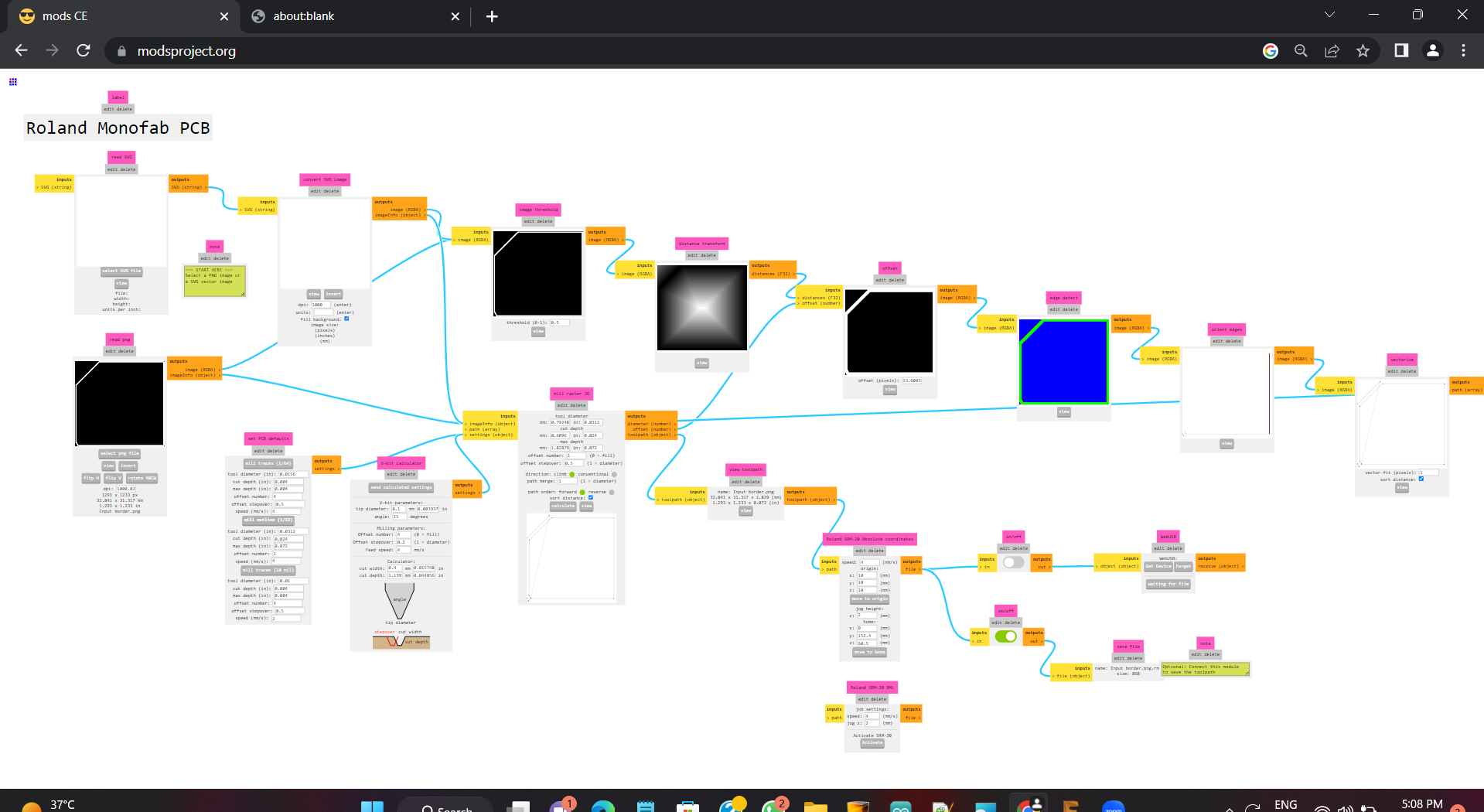
After that I open the v panel and and start milling my board. there is the image of My design board .
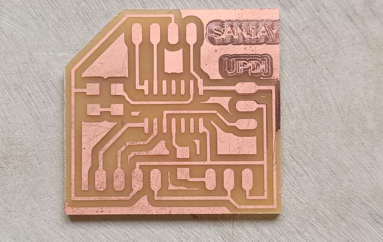
Soldering Process
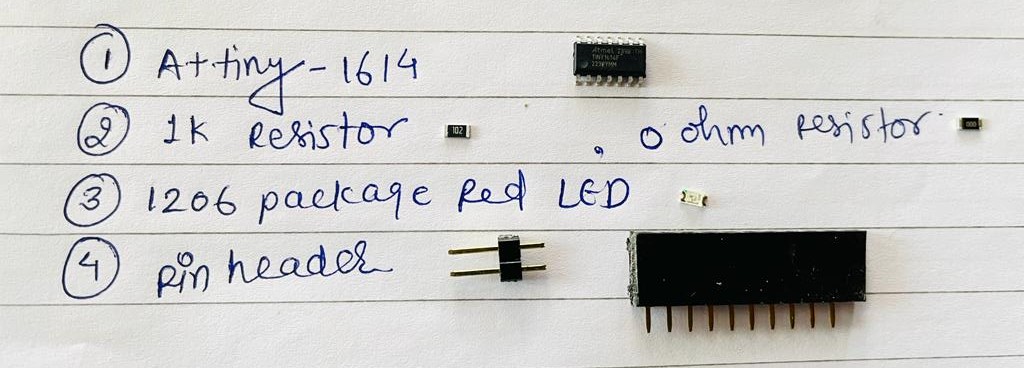
Component used-1. Attiny 1614
2. 1206 package 1K resistor and a LED
3. 4 Pin header *2
4. 3 Pin header *2
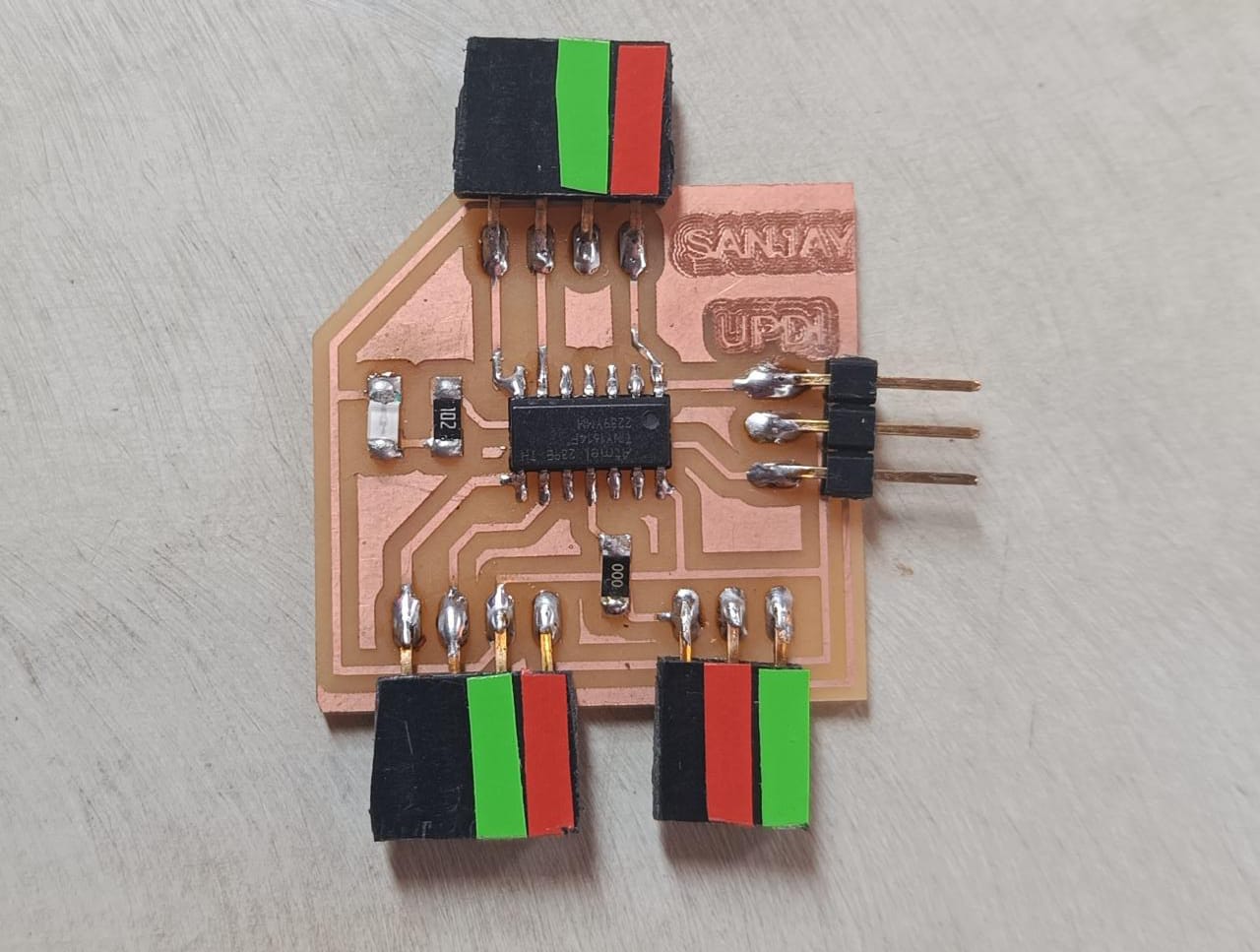
After soldeing all this component the on the board. then it is completed
Programming
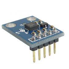
The most difficult part for me this week is to programme attiny 1614. We used its UPID pin for programming. So we need To a programmer which communicate between USB serial monitor and UPDI. So I mill the board which is provided in embeded programming week. This board have a FT230x Ic . We modify this board by adding an extra pin for the VCC.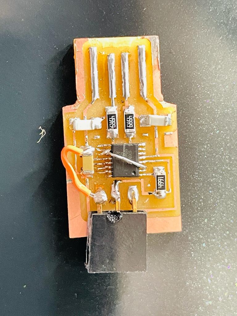
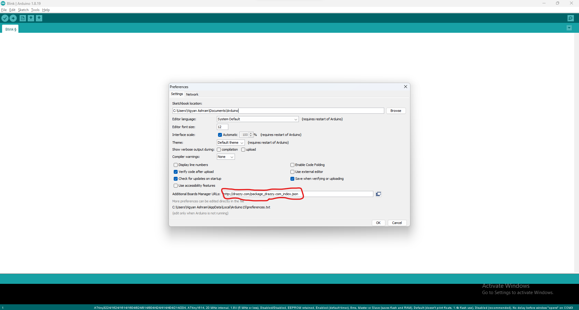
First time board was not run but after several trial We will able to prograame our board. We found that the board having gap between usb ports pins thats why it not connect with the laptop. So I stick a paper tape behind the board. After this its port visible. Now we have to add library of Attiny in the arduino ide. To add library follow the steps-
Go to file >> Preference >> and past the given link in url section.
Link to paste- "http://drazzy.com/package_drazzy.com_index.json"
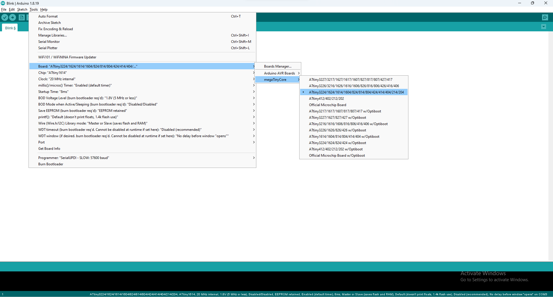
After that go to board manager and search "MegaTinycore" And install it. After that go to the tool option and select the mega tiny core and then select the attiny 1614 IC
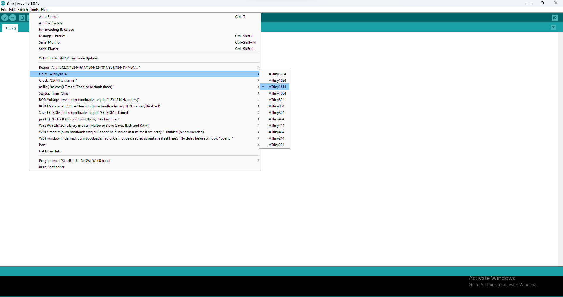
After that select chip as Attiny1614. Now go to the programmer and select "SerialUPDI Slow:57600 Baud".
NOTE- I also facing issue with arduino ide newer version. so I download the older version of Arduino Ide and it work.
Ultrasonic Sensor
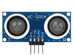
Ultrasonic sensor are used to measure the distance. It have two parts in module in which one part transmit the signal and another recieve the signal. It emits the frequency of 40KHz then this frequncy travel with the speed of sound and strike on the object and then return back to the reciver at module.
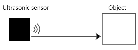
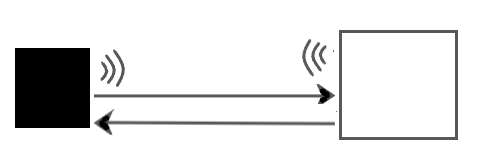
It have four pin ECHO, TRIG, VCC, GND. When we send the signal, the firstly trig pin high for some time then it become low and send the signal. When the module send the signal the echo pin become high and when we get the reflected signal the echo pine become low. Now we have to calculate the time for the ehigh value of echo pin. It can be easily undersatand by the following diagram
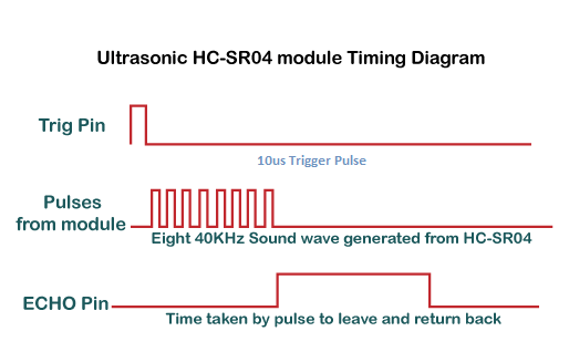
Now we have to define how the sensor measure the distance. We know that the speed of sound is 340m/sec. we convert this speed in cm per microsecond and become 0.034cm/us.
we know that Speed = distnace / time and the Time = Distance/Speed.
speed= speed of sound
Then Time= Distance/speed of sound
Distance= Time *speed of sound
now at this time it give the distace of total signal travel. We have to measure only the distance between the module and striking object. so we divided the Speed by 2. Distance = Time* Speed of sound/2 is the formula used to measure the distance.The same formula we used in arduino code. Now we connect the ultasonic to my PCB board.
Credit and Reference
Connection Diagram and coding-
I Short the Trig and echo pin and connect this pin to board pin (PB2) digital pin5. Then I go to example and take the ultrasonic ping code Then I modified the code by adding the code for oled and then after selecting port of UPDI Programmer and upload it. and connect oled display to the board to see the result.Code -
Code compiling and uploading
Result Video
When I move the Object in the front of sensor the value of distance is changes.It can be seen in display in given VideoLDR
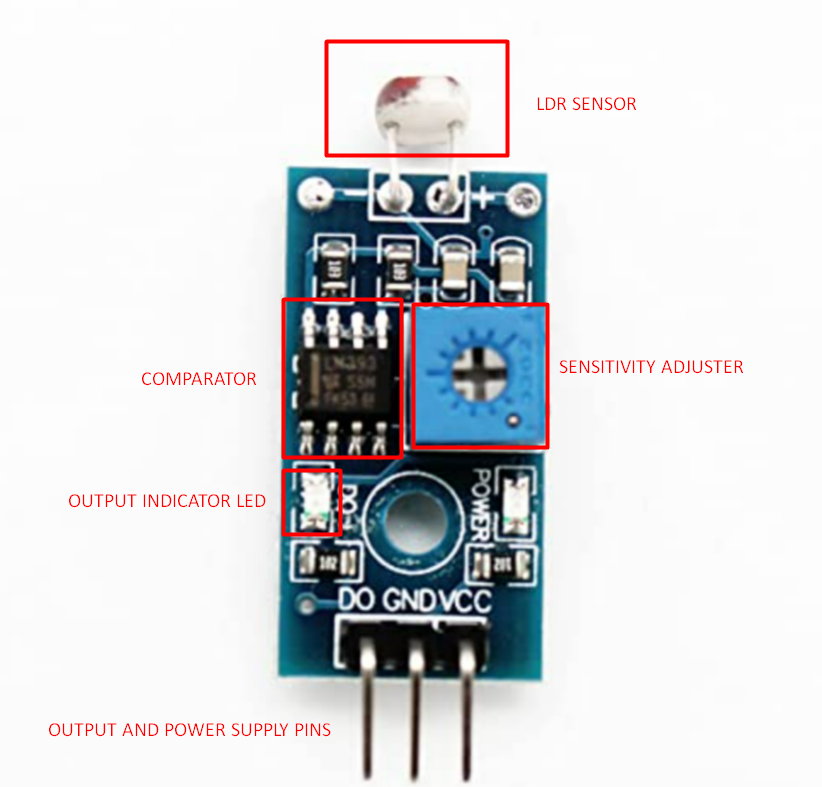
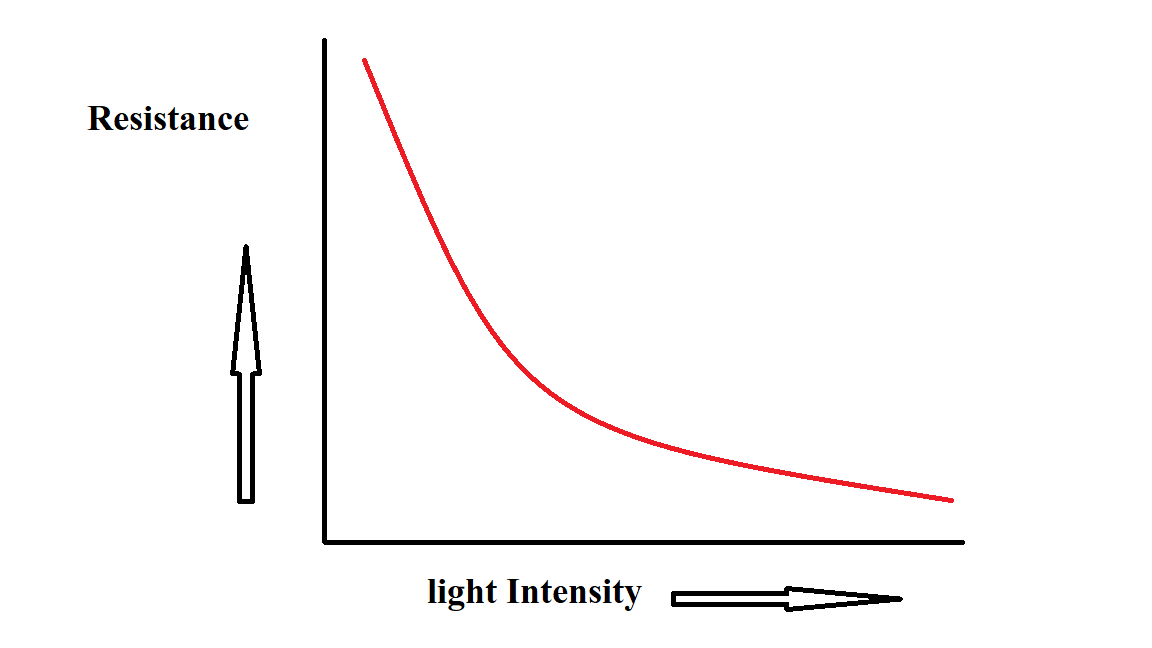
LDR means light dependent resistance.It is the type of resistor .It detect the intensity of light and give the signal to microcontroller. It resistance value decreases When the intensity of light increases and its resistance value increses when the light intensity decreases. This LDR Connect with module which convert its resistanve value into mV. This module have a comperatore which compare the value and give the output signal. Ldr sensor have two conduction layer. This layer contains electrons. When the light fall on the sensor theis electron get excited and travel between two conduction layer and reduce the resistance. another way when the light intensity decrease its resistance value increases. This ldr Module contain a comparator (LM393) Which compare the signal and according to it it give output value. It also have a output indication and power supply led. It have senstivity adjuster by which we change the ldr senstivity toward light intensity. When we rotate it clockwise its senstivity increases and when we rorarte it anticlockwise its senstivity decreases.The module i have used have only one output pin for digital signal means it give the value in the form of 0 and 1. I am connect the module signal pin in IC's Pin PA1(8) . connect the module and supply power to it.
Credit and Reference
Code-
Code compiling and uploading
Result Video
After uploadinf the code I do some changes in senstivity adjustor ldr module then when I cover the sensor it Gives high value(1) and when The light come it give the low value(0).Force by Step response
This is new for me. So I follow the Adrian Torres Blog for making this step response sensor. The sensor I am going to made is give response on force value. simply we have taking copper tape and cut them in 2 square pieces. after that I add a wire on both the copper pieces.Now I redesign the board which is act as module for this copper tape peices.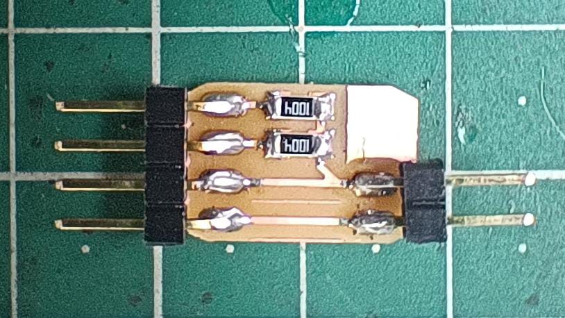
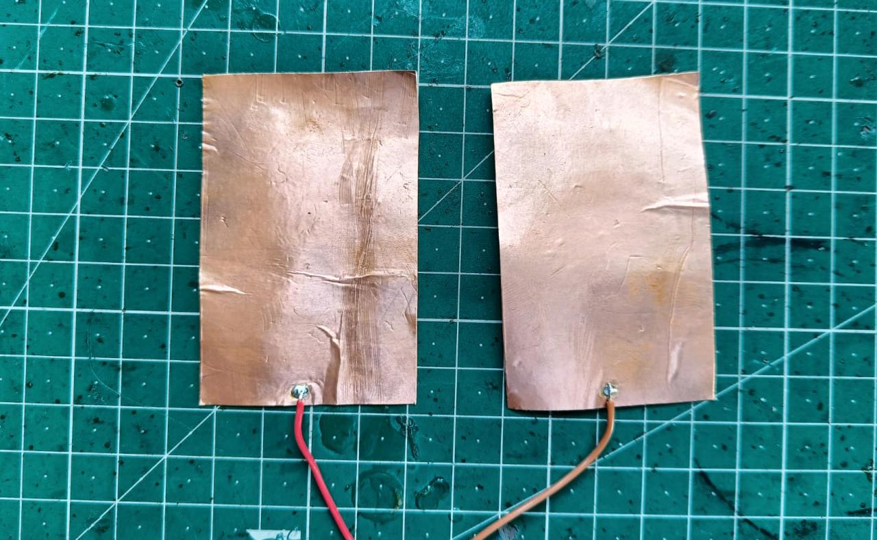
in this board we have to connect the copper foil. Now the one copper foil is connected To IC's digital pin for the output and act as Tx and another copper foil is connected to analog pin for the input and act as a Rx. This Rx pin is to coonected with 1M Ohm resistor as shown in diagram . This two resistor Act as pull up and Pull down resistor and they connect with the VCC and GND.
Working-
After adding the board with copper foil, It now act as a sensor and can measure force , Resistace ETC. at the time of working We provide a continous high value to the Tx pin and then I put the a copy on the two copper foil. The Copper foil connected with tx continously receive high signal from the board. when we provide load it craete a pathway to pass the magnetic field into another copper foil. Due to this magnetich force the Rx connected foil give some value to the microcontroller and it work like that.Code-
Code compiling and uploading
Result Video
Result Video
Learning outcomes
-I learned about different type of Sensor and know about their working.-I learned about The new ATTiny1614 and know about how to programme it.
-I designed a new board with Attiny 1614 on eagle.
-I learned about FT230X module which is used for programming the Attiny1614.
-I tried ultrasonic, LDR and step response sensor with my PCB Board.
What went well
-Board succesfully programmed after lots of trial.-All the sensor working fine .
-Tried the step response first time and it working Good but not have proper accuracy.
Issue Faced
-The Ft230X module are not working with new version of arduino so I download the Older one and it working fine.Download the all original file
Download FileDownload the code File